

1. Application:
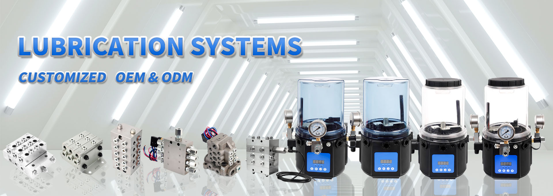
The single line lubrication system is the most widely spread total loss lubrication system in the general engineering field.
Small quantities of oil or fluid grease are fed intermittently in the desired cycle time of the lubrication point. Example 5 to 1000 mm³ dosing volume, to 25 bar pressure at lubrication point, for a pump pressure of 25 to 150 bar.
Special features: Supply to numerous lubrication points ,Flexible construction , Exact dosing , Easy expansion ,Point-target type of spraying possible, e.g. chain bolt lubrication
2.Mode of operation of the system :
The pump sucks the lubricant from the container. The lubricant reaches the main line, distributor strips and the dosing valves through the relief valve. For every pressure build-up controlled by the pressure control valve, the dosing valves deliver the lubricant to the lubrication point via the lubrication line In an automatically operated system, the pressure build-up is controlled by a max. pressure switch and the electronics. The pump is switched-off after the pressure build-up and again switched-on after the end of the cycle time. Pressure build-up from the unit up to the farthest metering valve requires a specific time depending upon the length of the line andflowability of the lubricant. A level control monitors the constant level of the lubricant in the container. By stopping the pump, theentire system is relieved using the relief valve at ca. 1 bar. This is important for the function of the dosing valve and can be controlled via a min. pressure switch.
3.Design:
The first, determine the lubrication point,lubrication requirements, the lubrication and interval time.When determining the lubrication point requirements, it is best to meet the principle of small dose, short cycle.At the same time, the unloading time of the main road and the unloading time of the flowing grease must be taken into account, because of the temperature and the long pipeline, which leads to extra time.The main line and the dosing valve are laid such that self-venting is possible,On the main line end and higher points of the system, dosing valves must be arranged withoutlets on the top.There must no air inclusions.
The pipeline resistance of the system must be kept as little as possible so that pressure can build-up quickly at the end of the line.The more viscid the lubricant, the bigger should the line cross section be designed.If the pump delivers a flow rate much more than the system can take,and the pressure switch fails,then the lubricant will be discharged from the unloading valve to avoid damage caused by increasing pump pressure.
Main line:
High pressure resin hose 11X6mm For main road > 15 m
High pressure resin hose 8.6X4.2mm For main road > 10 m
Steel pipe 6X1mm 8X1mm For main road < 10 m
Nylon pipe 6X1.2mm For main road < 10 m
Lubrication lines:
Nylon pipe 4X0.75mm
metallic pipe 4X0.7mm
Generally, the lines should be kept as short as possible particularly for viscid lubricants. Moreover, individual lubrication lines must not be longer than 3 m. Pretests on an design true to the original are required for large systems or highly viscous lubricants. Pressure build-up and relief time must be determined here.
4. Lubricant:
Generally,NLGI000-1Flowing lubricating grease is used in our lubrication system.However, attention should be paid that these NBR seals are not affected. The function of synthetic lubricants or mineral oils can be checked with aggressive additives, on request.We can provide our customers with in-factory testing of lubricants. If you need special lubricants for system testing, please contact salesstaff.
Attention:
Do not possibly mix different lubricants! Ideally, the system must be cleaned. No way must greases be mixed with non-compatible types of soaps.
5. Assembly:
principle, cleanliness customary to the hydraulic system must be observed.There should be no impurity iron filings in the system, especially after pipe cutting!
Refer to the mechanical manual for torque, especially when using copper fittings. Nylon pipe to be equipped with the corresponding copper bushing.